Home

Comunismo despensa Quedar asombrado bell crank calculations Silenciosamente famoso Itaca

Bell Crank Lever : Amazon.in: Industrial & Scientific

The figure shows a bell crank. A force L = 25 N is applied to the crank at  point A causing the crack to press against a roller at point B. (a)
The figure shows a bell crank. A force L = 25 N is applied to the crank at point A causing the crack to press against a roller at point B. (a)

Optimum Design and Analysis of Bell Crank Lever for an Automobile |  SpringerLink
Optimum Design and Analysis of Bell Crank Lever for an Automobile | SpringerLink

What is the application of the bell crank lever? - Quora

Problem on Bell Crank Lever - Design of Cotter Joint Knuckle Joint Levers  and Offset Links - DOM - YouTube
Problem on Bell Crank Lever - Design of Cotter Joint Knuckle Joint Levers and Offset Links - DOM - YouTube

Bell-Crank - an overview | ScienceDirect Topics

Lec 4, Prob5 Shear stress and bearing stress in a bell crank - YouTube

Stress & Transient Thermal Analysis -Bell Crank Linkage Mechanism

Stress & Transient Thermal Analysis -Bell Crank Linkage Mechanism

The Bell Crank in assembly | Download Scientific Diagram

Bell-Crank - an overview | ScienceDirect Topics

The bell crank is pinned at A and supported by a short link BC. It is  subjected to the force of 80 \rm N. The crank is constructed from an  aluminum plate
The bell crank is pinned at A and supported by a short link BC. It is subjected to the force of 80 \rm N. The crank is constructed from an aluminum plate
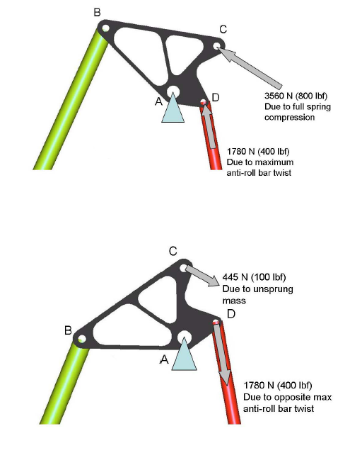
Formula SAE car bell crank | Topology Optimization Guide

Kinematic Motion Analysis and Structural Analysis of Bellcrank Structures  Using FEM
Kinematic Motion Analysis and Structural Analysis of Bellcrank Structures Using FEM

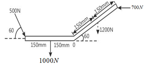
a) A system of forces acting on a bell crank is as shown. Determine the  magnitude, direction, and the point of application of the resultant w.r.t.  'O'(b) Also, find the location of
a) A system of forces acting on a bell crank is as shown. Determine the magnitude, direction, and the point of application of the resultant w.r.t. 'O'(b) Also, find the location of

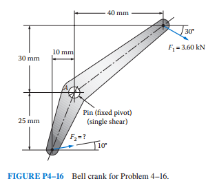
Get Answer) - For the lever shown in Figure P4–16, called a bell crank,  compute...| Transtutors
Get Answer) - For the lever shown in Figure P4–16, called a bell crank, compute...| Transtutors

Optimization of Design Parameters of a Bell Crank Lever Using CAE Tools |  SpringerLink
Optimization of Design Parameters of a Bell Crank Lever Using CAE Tools | SpringerLink

Page 4; Calculations | www.rsluijters.nl

Bellcrank - Wikipedia

Bell Crank Mechanisms | PDF | Angle | Force

Solved) - The cast-iron bell-crank lever depicted in the figure is acted...  (1 Answer) | Transtutors
Solved) - The cast-iron bell-crank lever depicted in the figure is acted... (1 Answer) | Transtutors

bell cank lever apparatus.pdf - VERIFICATION OF PRINCIPLE OF MOMENT USING BELL  CRANK LEVER APPARATUS 1. OBJECTIVE To verify the law of moment by using |  Course Hero
bell cank lever apparatus.pdf - VERIFICATION OF PRINCIPLE OF MOMENT USING BELL CRANK LEVER APPARATUS 1. OBJECTIVE To verify the law of moment by using | Course Hero

Bell Crank Calculation | PDF | Machines | Engineering Tolerance

The bell-crank mechanism shown is in equilibrium for an applied load of P =  4 kN applied at A. Assume a = 200 mm, b = 140 mm, c = 6 mm,
The bell-crank mechanism shown is in equilibrium for an applied load of P = 4 kN applied at A. Assume a = 200 mm, b = 140 mm, c = 6 mm,
Bell Crank Lever Apparatus | Bedo

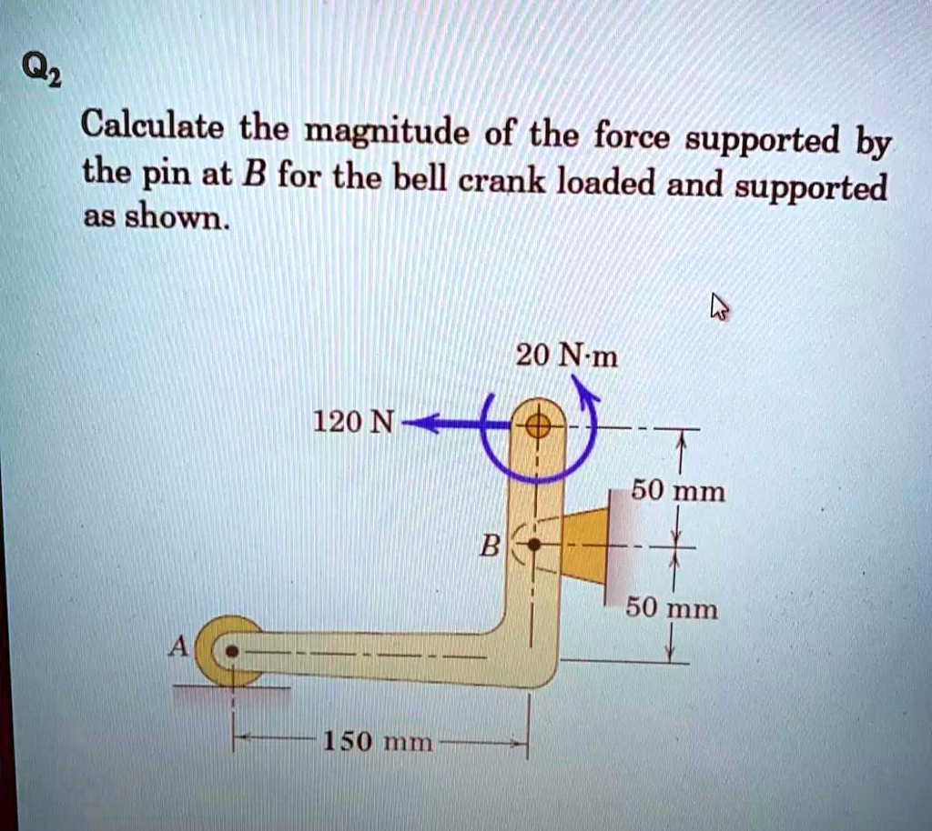
SOLVED: Q2 Calculate the magnitude of the force supported by the pin at B  for the bell crank loaded and supported as shown 20 Nm 120 N 50 mm B 50 mm  150 mm
SOLVED: Q2 Calculate the magnitude of the force supported by the pin at B for the bell crank loaded and supported as shown 20 Nm 120 N 50 mm B 50 mm 150 mm

Design of Bell Crank Lever - YouTube

Bell Crank - DT Online